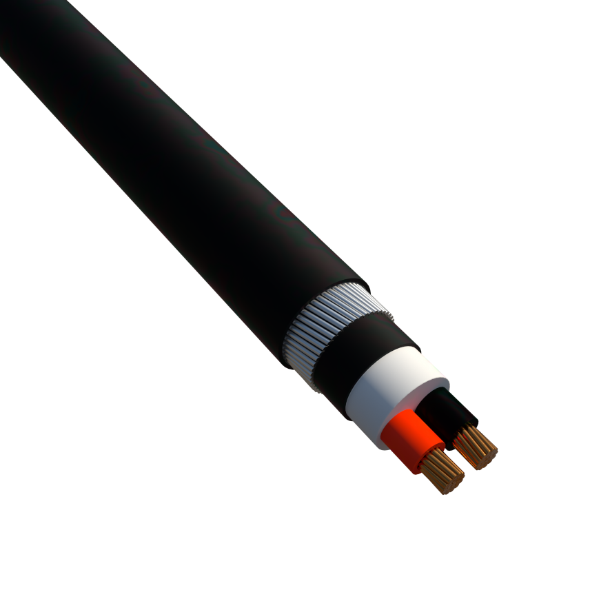
2C X 25 Sq.mm CU/XLPE/SWA/HFFR

2C X 25 Sq.mm CU/XLPE/SWA/HFFR
2-CORE XLPE,SWA,HFFR SHEATHED CABLES AS PER QCS 2014
Read more- Nexans ref. : 22025SXZHSH30BS0
Description
Description
Standards
-
ProductBS 6724
-
TestIEC 60332-3 Cat.C
Scope
This specification covers two core, XLPE insulated cables for use on the Qatar Power Systems ,Street lightning and Small wiring systems. These cables are complying with BS 6724 and QCS 2014 Standards .
Design
1. Conductor
Plain annealed high-conductivity Stranded Copper Class 2 conforming to BS EN 60228
2. Insulation
XLPE insulation Type GP8 conforming to BS 7655-1
3. Filling or Bedding
Extruded HFFR
4. Armour
Single layer of Galvanised Steel Wires (GSWA)
5. Outer Sheath
Halogen Free Flame Retardant (HFFR)
- Flame retardant : IEC60332-3-24 CAT C
- Colour : Black
Marking
NO.OF CORES X Sq.mm CU/XLPE/SWA/HFFR 600/1000 V BS 6724 MADE IN QATAR QICC-NEXANS Years Meters
Characteristics
Characteristics
Construction characteristics
Construction characteristics
Conductor material
Copper
Conductor shape
Circular
Conductor flexibility
Stranded class 2
Armour type
Galvanized steel wires
Colour
Black
Core identification
Red,Black
Halogen free
Yes
Inner sheath
Halogen free flame retardant
Insulation
XLPE
Outer sheath
Halogen free flame retardant
With Green/Yellow core
No
With smaller neutral conductor
No
Dimensional characteristics
Dimensional characteristics
Number of cores
2
Conductor cross-section
25 mm²
Approximate weight
1056 kg/km
Neutral conductor section (when smaller)
- mm²
Nominal armour wire diameter
1.6 mm
Nominal insulation thickness
0.9 mm
Nominal outer diameter
22.4 mm
Electrical characteristics
Electrical characteristics
Rated Voltage Uo/U (Um)
0,6/1 kV
Max. DC resistance of the conductor at 20°C
0.727 Ohm/km
Permissible current rating in open air
131 A
Permissible current rating when buried
107 A
Thermal soil resistivity dry zone
2.5 °K.m/W
Voltage drop, 3 conductors
1.7 V/A.km
Usage characteristics
Usage characteristics
Max. conductor temperature in service
90 °C
Short-circuit max. conductor temperature
250 °C
Bending factor when laying
12 (xD)
Ambient air temperature
30 °C
Ambient ground temperature
20 °C
Laying depth, center of system
700 mm
Max. pulling force during laying
50 N/mm2
Resources
Resources
Our websites
Select your country to find our products and solutions
-
Africa
- Africa
- Ghana
- Ivory Coast
- Morocco
- North West Africa
- Americas
- Asia
- Europe
- Oceania